Thursday, December 10, 2009

Verilog code's

bidirectional buffer
module bidirectionalbuffer(A,B,C,sel);
inout [7:0]A; //bus
input [7:0]B; //tx
output [7:0]C; //rx
input [2:0]sel;


genvar j;
generate for(j=0;j<8;j=j+1) begin :buffif_loop1
bufif1 m1 (B[j],A[j],sel[0]);// bus to tx
bufif1 m2 (A[j],C[j],sel[1]); // rx to bus
end
endgenerate
endmodule


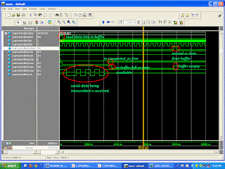
timing diagram

UART Verilog code with testbench

reference www.asic-world.com
module uart2 (
reset ,
txclk ,
ld_tx_data ,
tx_data ,
tx_enable ,
tx_out ,
tx_empty ,
rxclk ,
uld_rx_data ,
rx_data ,
rx_enable ,
rx_in ,
rx_empty
);
// Port declarations
input reset ;
input txclk ;
input ld_tx_data ;
input [7:0] tx_data ;
input tx_enable ;
output tx_out ;
output tx_empty ;
input rxclk ;
input uld_rx_data ;
output [7:0] rx_data ;
input rx_enable ;
input rx_in ;
output rx_empty ;
wire rx_in;

assign rx_in=tx_out ; // connect receiver to transmitter interconnect
assign uld_rx_data=~rx_empty; // unload data when rx buffer is full
// Internal Variables
reg [7:0] tx_reg ;
reg tx_empty ;
reg tx_over_run ;
reg [3:0] tx_cnt ;
reg tx_out ;
reg [7:0] rx_reg ;
reg [7:0] rx_data ;
reg [3:0] rx_sample_cnt ;
reg [3:0] rx_cnt ;
reg rx_frame_err ;
reg rx_over_run ;
reg rx_empty ;
reg rx_d1 ;
reg rx_d2 ;
reg rx_busy ;

// UART RX Logic
always @ (posedge rxclk or posedge reset)
if (reset) begin
rx_reg <= 0;
rx_data <= 0;
rx_sample_cnt <= 0;
rx_cnt <= 0;
rx_frame_err <= 0;
rx_over_run <= 0;
rx_empty <= 1;
rx_d1 <= 1;
rx_d2 <= 1;
rx_busy <= 0;
end else begin
// Synchronize the asynch signal
rx_d1 <= rx_in;
rx_d2 <= rx_d1;
// Uload the rx data
if (uld_rx_data) begin
rx_data <= rx_reg;
rx_empty <= 1;
end
// Receive data only when rx is enabled
if (rx_enable) begin
// Check if just received start of frame
if (!rx_busy && !rx_d2) begin
rx_busy <= 1;
rx_sample_cnt <= 1;
rx_cnt <= 0;
end
// Start of frame detected, Proceed with rest of data
if (rx_busy) begin
rx_sample_cnt <= rx_sample_cnt + 1;
// Logic to sample at middle of data
if (rx_sample_cnt == 7) begin
if ((rx_d2 == 1) && (rx_cnt == 0)) begin
rx_busy <= 0;
end else begin
rx_cnt <= rx_cnt + 1;
// Start storing the rx data
if (rx_cnt > 0 && rx_cnt < 9) begin
rx_reg[rx_cnt - 1] <= rx_d2;
end
if (rx_cnt == 9) begin
rx_busy <= 0;
// Check if End of frame received correctly
if (rx_d2 == 0) begin
rx_frame_err <= 1;
end else begin
rx_empty <= 0;
rx_frame_err <= 0;
// Check if last rx data was not unloaded,
rx_over_run <= (rx_empty) ? 0 : 1;
end
end
end
end
end
end
if (!rx_enable) begin
rx_busy <= 0;
end
end

// UART TX Logic
always @ (posedge txclk or posedge reset)
if (reset) begin
tx_reg <= 0;
tx_empty <= 1;
tx_over_run <= 0;
tx_out <= 1;
tx_cnt <= 0;
end else begin
if (ld_tx_data) begin
if (!tx_empty) begin
tx_over_run <= 0;
end else begin
tx_reg <= tx_data;
tx_empty <= 0;
end
end
if (tx_enable && !tx_empty) begin
tx_cnt <= tx_cnt + 1;
if (tx_cnt == 0) begin
tx_out <= 0;
end
if (tx_cnt > 0 && tx_cnt < 9) begin
tx_out <= tx_reg[tx_cnt -1];
end
if (tx_cnt == 9) begin
tx_out <= 1;
tx_cnt <= 0;
tx_empty <= 1;
end
end
if (!tx_enable) begin
tx_cnt <= 0;
end
end

endmodule
downloadclick

test bench for the above
module uartcontroller(data,load,unload,rxen,txem,rxem,txen,reset,rxin,txout,clkL,clkH);
inout [7:0]data;
output load;
output clkL,clkH;
output unload;
output rxen;
output txen;
output reset;
input txem,rxem;
reg txemt;
reg rxemt;
output txout;
input rxin;
reg clkL,clkH;
wire rxen,txen;
reg reset;
wire [2:0]sel;
wire [7:0]datain,dataout;
uart m1(
.reset(reset) ,
.txclk(clkH) ,
.ld_tx_data(load) ,
.tx_data(datain) ,
.tx_enable(txen) ,
.tx_out(txout) ,
.tx_empty(txem) ,
.rxclk(clkL) ,
.uld_rx_data(unload) ,
.rx_data(dataout) ,
.rx_enable(rxen) ,
.rx_in(rxin) ,
.rx_empty(rxem)
);
assign rxin=txout;
assign sel[0]=load;
assign sel[1]=unload;
bidirectionalbuffer m2(.A(data),.B(datain),.C(dataout),.sel(sel)); // using same data lines for loading data into tx register and reading data from rx buffer
initial begin
clkL<=1'b0;
clkH<=1'b0;
reset<=1;
#10 reset <=0;
end
// clock generation
always
#10 clkL<=~clkL; // clock for rx

always
#160 clkH<=~clkH; // clock for tx
endmodule


happy coding

Neural Network's Matlab

using NNTOOL
here we will be training a network to recognize a particular pattern
first we have to normalize the data.......
let the data be (X)
2 5 6 3 1
5 2 2 5 1
4 4 5 4 4
1 5 2 4 5
1 6 6 6 6
3 6 3 2 1
6 4 2 5 4
3 1 2 5 3
4 1 4 3 1
2 2 3 4 3

each column a particular pattern
first find the minimum value from each column and subtract
the same then divide the whole column with the max value (column)
ull get data something like this (x=rand(10,5))

0.5822 0.5447 0.4046 0.6963 0.3477
0.5407 0.6473 0.4484 0.0938 0.1500
0.8699 0.5439 0.3658 0.5254 0.5861
0.2648 0.7210 0.7635 0.5303 0.2621
0.3181 0.5225 0.6279 0.8611 0.0445
0.1192 0.9937 0.7720 0.4849 0.7549
0.9398 0.2187 0.9329 0.3935 0.2428
0.6456 0.1058 0.9727 0.6714 0.4424
0.4795 0.1097 0.1920 0.7413 0.6878
0.6393 0.0636 0.1389 0.5201 0.3592


let the output of each pattern be(y=rand(1,5))
0.7363 0.3947 0.6834 0.7040 0.4423
output corresponding to each column,normalized
x(:,1)-->y(1,1)
x(:,2)-->y(1,2) lly

type nntool at matlab command window another window named
Network/Data Manager will pop up


click on import button and export x as input data and y as target data !

ull get a message like this


after this close import window ,now ur network/data manager window will look like this

now click on new button ull see another window here u have to select the type of NN u want to create
we will be create a feedforward back propagation NN most popular one
der u select the inputs and target data


then click on create and close that window
now u should be able to see a network in network/data manager window(middle)
click on that newly created network (icon) then click on open
ull see another window


click on train tab -> then training info
add inputs and targets as x,y then click on train network ....wait for some time ull see a graph once the
goal is met click on stop training button and close that graph and this window ..
now our NN is trained and is read for testing ........ hurray
after this click on export button in network/data manager ....
now close this window ..u should be able to see ur trained network in ur matlab work space......

now use this command
output=sim("networkname","data")
example
output=sim(network1,x(:,1))
which should be same as y(1,1)
u can test ur network reliability by adding noise .....
ur rand function for this purpose

thats it ........
thks

Sunday, November 29, 2009

Scrolling message display board

To make an led ON/OFF we usually use one I/O pin of the microcontroller
this will work fine with 5 to 8 leds but when u have drive a display board
which may contain LEDs between 70 to 100 depending on the matrix size , using each microcontroller I/O to control each LED is impossible and !!!!!!!!

so there are ways in which we can control many leds using few i/o pins
1)using charlieplexing if we have n i/o pins we can control
n*(n-1) leds using this method and all the pattern's may not be possible in this case
more about charlieplexing can be found at charlieplexing

charlieplexing with 3 i/o pins


2)using Dot Matrix
leds a connected like this


two types common anode n common cathode type.....
u can buy this modules , they cost around Rs70(5*7 matrix)


here we send data row wise , that is activating one row at a time and through column we need to send the data which we want to see
this image might give a better idea


i have shown for two row's this repeat's in a loop for all the row ..

3) using decoder's this is the ultimate way and flickering can be seen if the microcontroller is working at slow speed's , we can control 1024 leds with 11 i/o pins two 5*32 decoder for row n column
we are not interested with this method , as modules are not available we need solder the whole LED network

Program which i have implemented
ATmega32 chip running @4mhz
compiler WINAVR

#include
#define F_CPU 4000000UL
#include
typedef unsigned char u8;
typedef unsigned int u16;

int main(void)
{
u16 data2[5]={1,2,4,8,16},y[5];
u16 i,j,k,p,t,l[5][6]={{0x7f,0x41,0x41,0x41,0x3e,0x00},{0x3e,0x41,0x41,0x41,0x3e,0x00},{0x7f,0x40,0x40,0x40,0x40,0x00},{0x7f,0x40,0x40,0x40,0x40,0x00},{0x01,0x02,0x7c,0x02,0x01,0x00}};//data to be displayed
DDRD=0X00; //control i/p for Lb and Rb
PORTD=0XFF; //internal pull ups
DDRA=0xff;//data O/p to dot matrix
DDRC=0xff; //control o/p to dot matrix
for(i=0;i<5;i++)
{
y[i]=0;
}

while(1)
{
for(i=0;i<5;i++)
{
for(p=0;p<6;p++)
{
// display data
for(j=0;j<50;j++)
{
for(k=0;k<5;k++)
{
PORTC=data2[4-k];
PORTA=y[k];

_delay_ms(1);

}
}
// next loop data
for(t=0;t<4;t++)
{
y[4-t]=y[3-t];
}

y[0]=l[i][p];//new data

}// end of p for

}// end of i for
}// end while

}

here's the vedio moving message vedio

PING PONG game on DOT matrix

Wednesday, November 25, 2009

charecter segmentation matlab


we will use the above image for processing

1.add the image to matlab work space

ch=imread('char.jpg');

2.convert the RGB image to gray scale using rgb2gray function
Gch=rgb2gray(ch);

3.convert this gray scale image to BW comparing with some threshold
bw= im2bw(Gch,graythresh(Gch));

now u will get a binary image containing 1 r 0 's which will be easy to process

4. find the edge's in that binary image
Ibw= edge(uint8(bw));
imshow(Ibw);

5.using Morphological process to enhance the image
se = strel('disk',4);
bw2 = imdilate(Ibw, se);
imshow(bw2);


6. filling the holes in the dilated image
fill= imfill(bw2,'holes');
imshow(fill)
7. labeling the parts of the image and marking their position
[lab n] = bwlabel(fill);
props = regionprops(lab);
Z = [props.BoundingBox];
Z= reshape(Z,[4 n]);


8. display the results
imshow(I);
hold on;
for i = 1:n
rectangle('position',z(:,i),'edgecolor','r');
end


this can be used with a neural network to recognize patterns
we will see how to do this in next blog

Friday, October 16, 2009

Robotic eye

Real time tracking of objects is an exciting idea , now we will see how exactly to track
a coloured object
im using Matlab version R 2007b

1)CODE for video initializations

vid=videoinput('winvideo',1,'RGB24_640x480') ; // specifies the size of captured input image and format
triggerconfig(vid,'manual'); // triggering type
set(vid,'FramesPerTrigger',1); // frames acquired for trigger
start(vid); // start video capturing

after executing u can see an vid named object in ur workspace


2)How to get the image

trigger(vid);
temp= getdata(vid,1);

trigger the vid object , and then the frames will be logged onto buffers u can retrieve them using getdata function
In this code Temp object will have image 640x480 ,use this for processing

3) RBG colour space
temp is an 640x480 array and each element in the array has 3 slots (each of one byte) for RED GREEN BLUE
actually the input image is 3D array
accessing each element temp(X,Y,COLOUR);
temp(1,1,1) ; first element in R dimension
lly for green 2 and blue 3,

4) Extract region of interest colour
matlab supports an inbuilt function roicolor();

usage
BW1 = roicolor(temp(:,:,1),0,20); // BW1 has 1 where the values of temp(:,:,1) in between 0 and 20 and 0 else where
BW2 = roicolor(temp(:,:,2),0,20);
BW3 = roicolor(temp(:,:,3),0,20);

BW= BW1 & BW2 & BW3; // this is the final BW image

the values given to the roicolour will vary with light intensity and need to be calibrated again and again ...... :(

for example u want to follow a blue colour object first get a snapshot of ur object
then find the max and min value in RGB space in ur region of interest(object)
then feed those value
this can be done using roipoly() function and a median filter or average filter

5) Calculate center of gravity of the image
BW will have 1's where the object is present and zeros elsewhere
u can get Xavg and Yavg values and mark the object in the given image temp

6)Improvements : This is one way of doing but this is not that efficient in noisy environment
to get a more robust program which u can really upon go for morphological image processing techniques
BW has a lot of noise we have to filter it out using erosion followed by dilation
to get a smoothed BW image

this is what i got after all those 5 steps and adding noise rejection capability
vedio

This is one method , this does not given exact envelop of the object we are tracking we can only pinpoint its location
to enclose the object in a box if have used histogram analysis and this is 0.1 sec faster than the above method
and the diagonal intersection of the box will given u the center of gravity which more accurate
here's the vedio
click